FAQs
Design and selection
We provide several motor drive modules with different sizes, voltage, power rating and control interface. Use our product selector to choose the one you need: Servo Drive Modules. The selector will show the eligible modules according to the filter criteria you set:
PCB Type: We have classified the modules according to their function. You can quickly find the one you need based on this filter criteria.
Motor Size: Basically, you need to select the right flange size of your motor so that the modules selected out can be properly mounted on it.
Control Interface: The available control interface includes RS485, CANopen, I/O, EtherCAT and so on. You can choose the appropriate ones for your application.
Voltage: This filter criteria shows the minimum and maximum voltage that your servo system can afford.
Power: This filter criteria describes the continuous power of modules.
Operation Mode: The available operation mode includes Speed/Position Control, Homing and so on. Choose what your application needs.
Once you finish your configuration of the filter criteria, the selector will show all the eligible modules in the table below. You can click the part number to turn to the product detail page and learn more about it. Meanwhile, the corresponding 3D model will be provided to help you design the mechanical parts.
Please check the typical voltage and power on the specification of the module or the all-in-one servo.
The output voltage range of the selected power supply should cover the typical voltage of the product mentioned above.
Meanwhile, for there may be spikes on the power, it is recommended that the output power of the power supply be 3 times higher than the maximum continuous output power of the product. The lack of input power supply may trigger the undervoltage protection of the servo system and lead to system reset.
Please check the voltage range on the specification of the all-in-one servo motor. If the voltage that you can provide is in the voltage range, the motor will still work properly.
Generally, the motor speed is proportional to the voltage. Thus, in this case, the motor is unable to reach the nominal maximum speed.
The output power is proportional to the voltage as well, which demonstrates that the maximum power of the motor will decrease if the supply voltage is lower than the typical one.
Define: k1 = (motor speed)/(actuator speed), where motor speed is the nominal speed that your motor outputs and actuator speed is the nominal speed that your application actually needs.
Define: k2 = (actuator torque)/(motor torque), where the motor torque is the nominal torque that your motor outputs and actuator torque is the nominal torque that your application actually needs.
Define: k is the gear ratio.
You can select your gear ratio k according to the following equation: k2 < k < k1.
It depends. The motors and modules in the size of 40mm and 42mm are compatible and ones in the size of 57mm and 60mm are compatible. But the 40mm module is not compatible with the 57mm motor and so on.
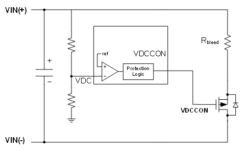
The regenerated energy will cause the DC voltage rising which may damage the device when it becomes too high. In this case, you can add an energy dispatching resistor controlled by a power MOSFET to absorb the energy. When the controller sensed the voltage rising, it will turn on the MOSFET so the DC voltage will not rise too high.
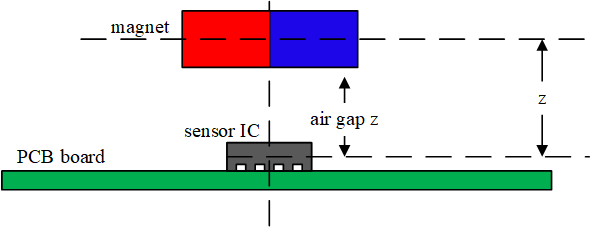
As the EZmotion modules use a magnetic position sensor to detect the rotor position, a magnet must be attached at the center of the motor rear shaft.
To choose the magnet: A sintered NdFeB or SmCo magnet with a 6 or 8 mm diameter and 2.5 to 3mm height with remnant field strength in the range 1.0 to 1.2 T is recommended. The diameter of the magnet will depend on the specific motor shaft and holder design used. Meanwhile, it is important that the magnetization is diametrically polarized.
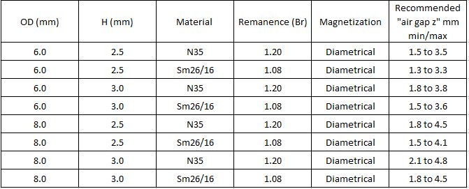
To design the air gap: The magnet airgap spacing to the sensor surface should be set to achieve a field strength in the range of 30mT min to 80mT max and the center of the magnet should be aligned with the center of the module. You can select the recommended magnets specifications according to the reference table below.
Cyclic redundancy check (CRC) is a method commonly used in digital networks and storage devices to detect burst errors. The transmitted data frame gets a short check value attached with a fixed length, based on the remainder of a polynomial division of its data segment. On the receiver side, the calculation is repeated. In the event that the check values do not match, corrective action can be taken against data corruption.
Cyclic redundancy check (CRC) is named because the check value is a redundancy, which expands the data frame without adding effective information, and because the algorithm is based on cyclic codes.
The CRC function is enabled by default. No additional input is required.
If a CRC error is detected, which means the data is unreliable, the EZmotion servo system ignores this data frame and does not send a response to the master. This causes a timeout event on the master side. The master device then reacts to the timeout event, so that the device is not trapped in a continuous wait state.
EZmotion uses CRC-16 as the parametric model, for which the generator polynomial is 0x8005.
Troubleshooting
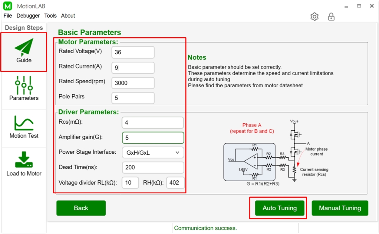
We provide the parameter identification and loop auto-tuning method to automatically tune parameters of the control loop. You can use it on the "Guide" page of the MotionLAB. Click here to learn more about How to setup the MotionLAB.
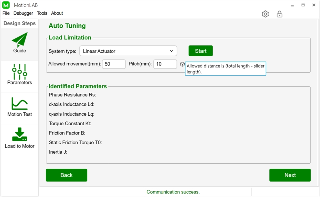
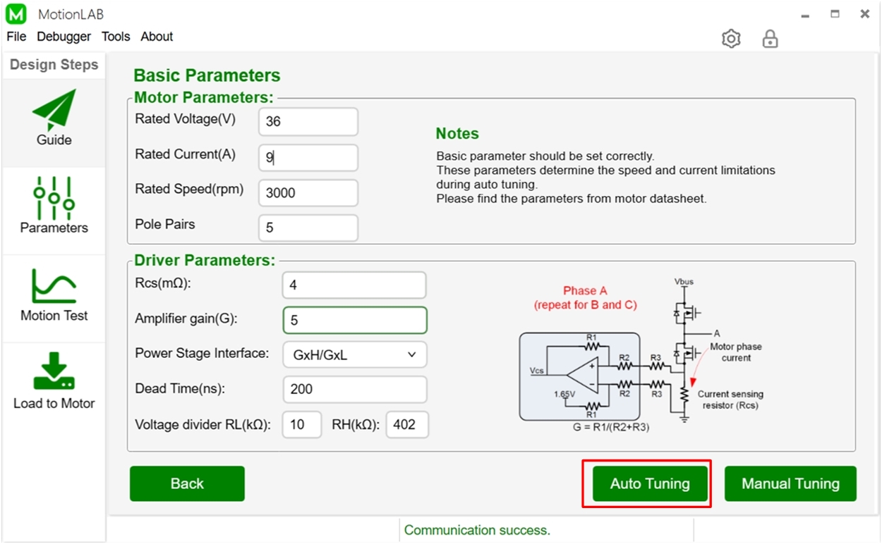
Step 1: Set the basic parameters properly before auto tuning. After finishing setting the parameters, click the "Auto Tuning" button to turn to the next page.
Step 2: Select system type and set corresponding parameters, then click "Start". The motor will run for a few seconds and the identified parameters will update. After the auto tuning is completed, click “Next” and the basic and details parameters page will be displayed.
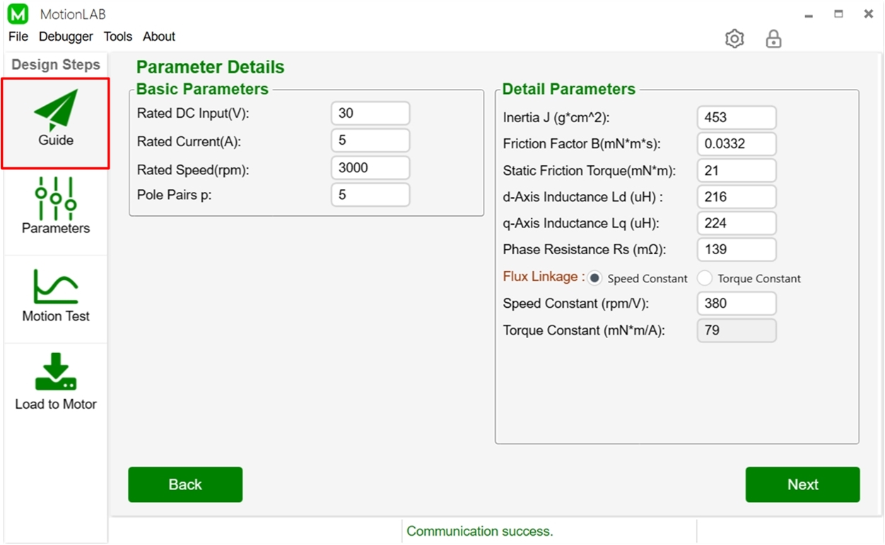
Step 3: The parameter details page will show the basic and detailed parameters of the servo system. You can manually adjust them.
The auto-tuning method will automatically calculate and set the parameters of the control loop according to the given bandwidth and estimated motor parameters. You don't need to do any extra operations.
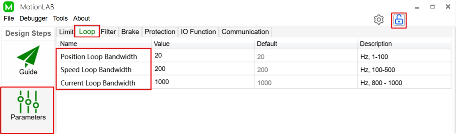
When selecting the loop bandwidth, the following tradeoff has to be taken into account: Higher speed and position loop bandwidth lead to better dynamic response but causes more vibration and noise.
For the current loop: The current loop is the innermost loop. The input is the current command, and the output is the voltage reference. The recommended bandwidth setting is 1kHz to 2kHz and a good start is 1kHz.
For the speed loop: The input of the speed loop is the speed command, and the output is the reference of the current loop. The recommended bandwidth setting is 50Hz to 400Hz. A good start is to set a bandwidth of 200Hz. The speed loop bandwidth should be set 5-10 times smaller than the current loop bandwidth.
For the position loop: The position loop is the outermost loop, and is used to control the motor position. The input is the position command, and the output is a speed reference for the speed loop. The recommended bandwidth setting is 10Hz to 100Hz; a good start is 50Hz. The position loop bandwidth should be set 5-10 times smaller than the speed loop bandwidth.
You can set the parameters mentioned above on the "Parameters" page of the Monolthic MotionLAB and save your design to a file or download it to the motor on the "Load to Motor" page.
There are two ways to minimize the position following error.
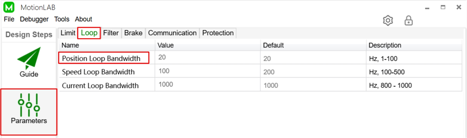
One way is to increase bandwidth of control loop, which will make the motor response faster to the position command. You can use the MotionLAB to set the bandwidth of the position control loop, you can adjust the value based on the default and the suggested range offered by description. Higher position bandwidth leads to better dynamic response but causes more vibration and noise.
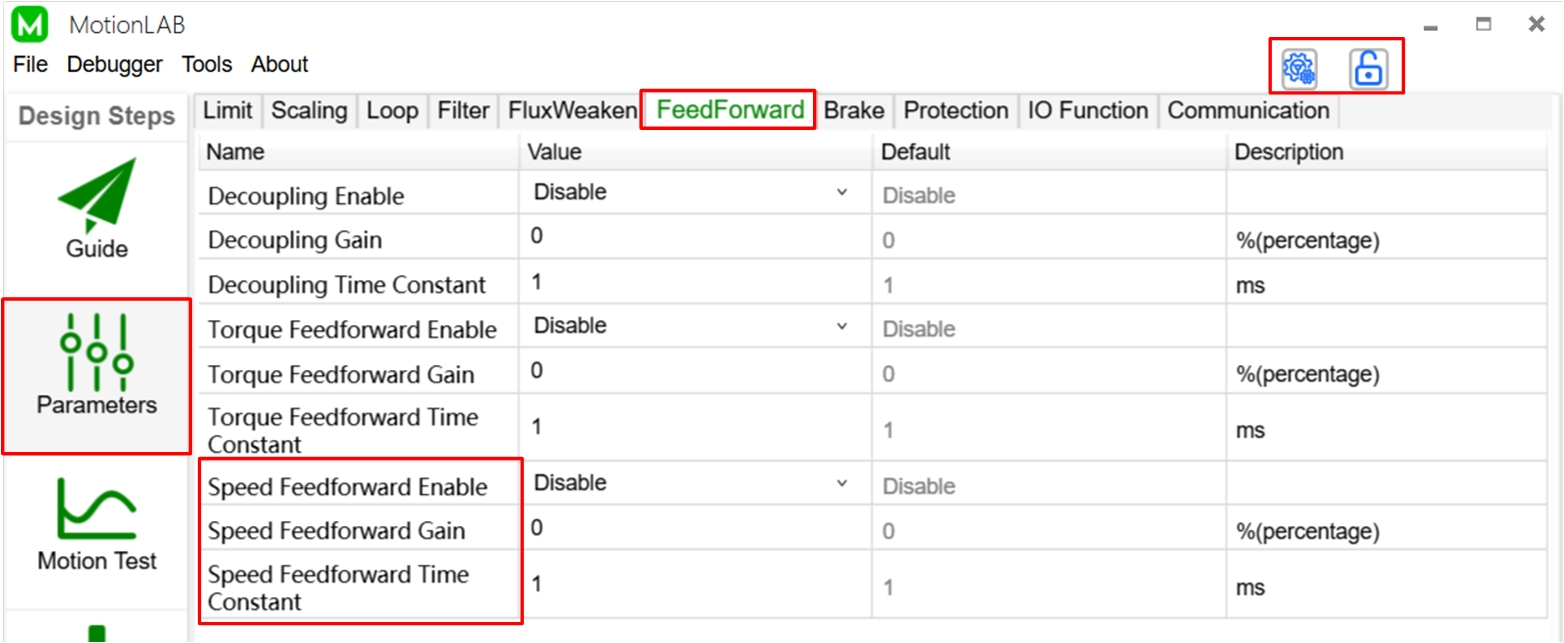
The other way is using feed-forward control. Speed feed forward can be used to minimize the position following error. See below block diagram, if the position reference is changed, the speed reference will change immediately, without the delay of the position control loop. You can enable the speed feed forward function and set the gain (in percent) and time constant (in ms) on the "Parameters" page of the MotionLAB. Click the "Basic/Advanced Settings" button to show the advanced parameters and click the "Lock/Unlock Parameters" button which allows you to configure the parameters. Then you can set "Speed Feedforward Enable/Gain/Time constant" in the section of "FeedForward".

After finishing the configuration, you can evaluate the position tracking performance in the "Motor Test" page and save your settings to a file or download it to the motor in the "Load to Motor" page.
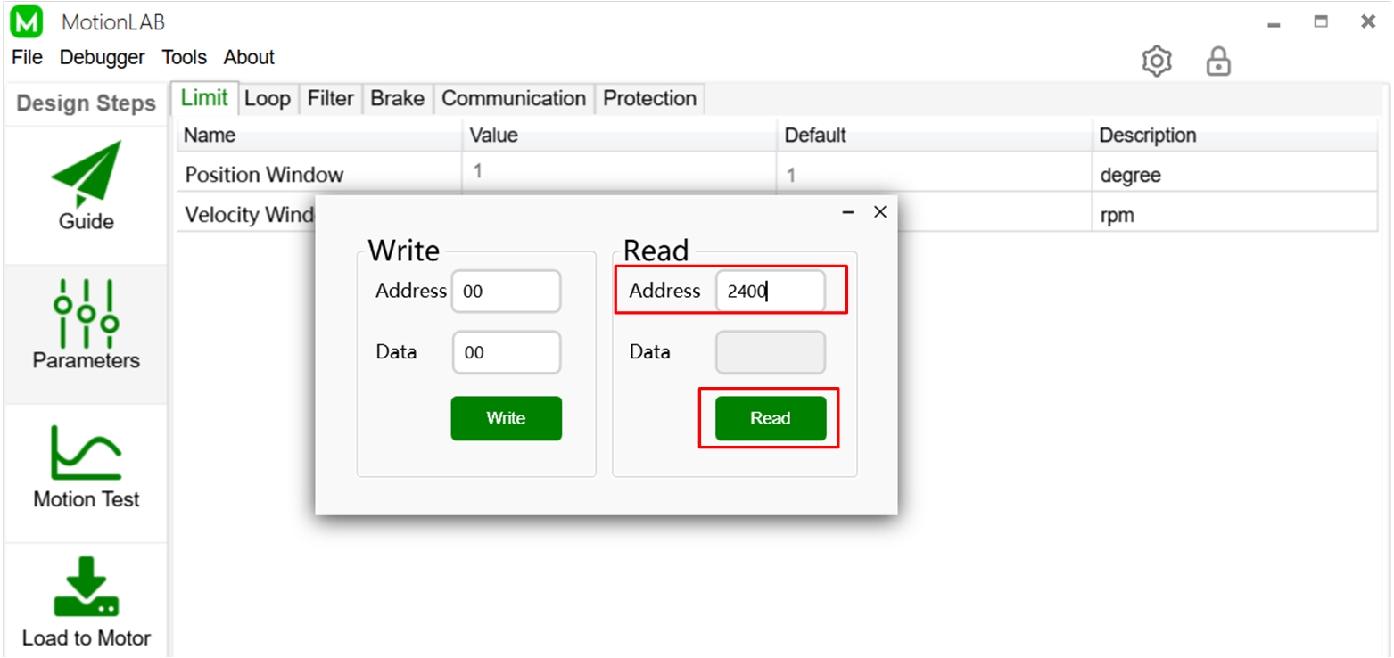
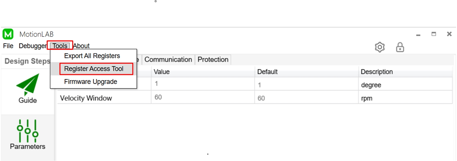
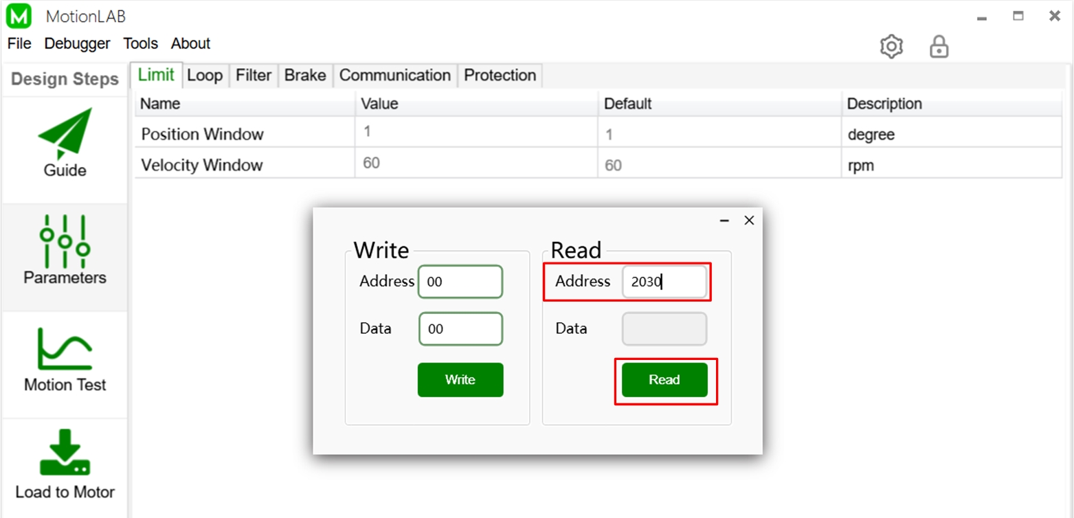
Normally, the power stage is where the temperature is highest when the servo motor operates. Thus, we locate the temperature sensor here to monitor the operating temperature. You can read the operating temperature via "Register Access Tool". You can find it in the tool bar: Tools -> Register Access Tool. Type the register address of temperature and click "Read" button, then the "Data" will illustrate the value. The register information is listed below for your reference.


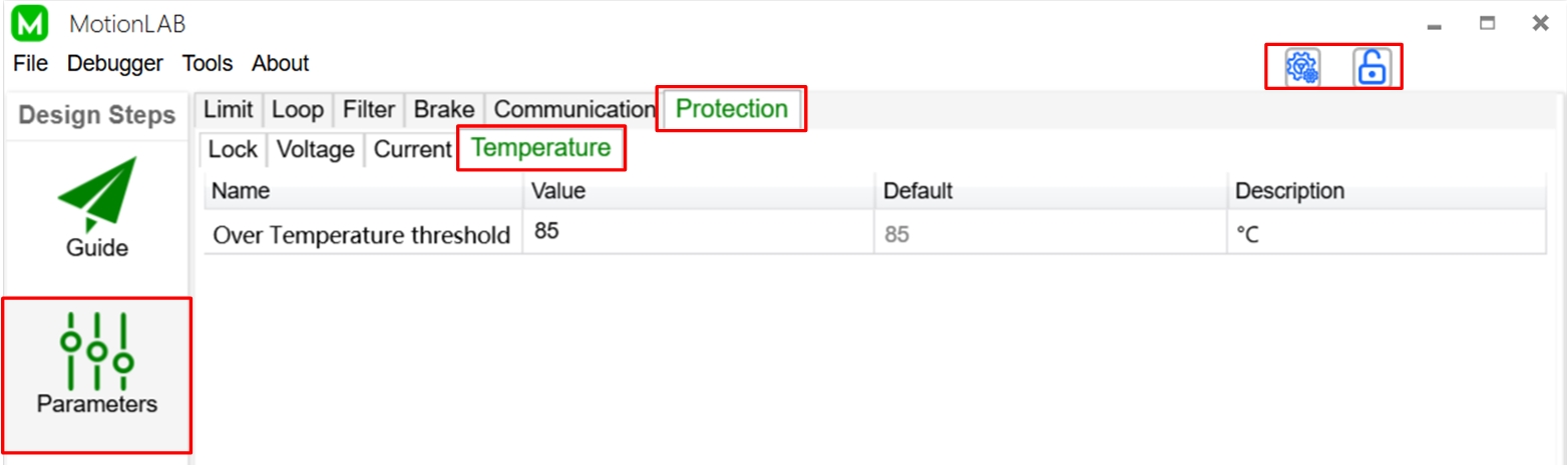
If there is an NTC thermistor connected to the NTC pin of the controller, over-temperature protection can be achieved. When the sensing temperature exceeds the set value, over-temperature protection is triggered. The module does not shut down the power stage when over-temperature protection is triggered. It sends a fault signal, and lets the user decide what to do in this condition.
You can set the over temperature threshold on the "Parameters" page of the MotionLAB. Click here to learn more about "How to set up MotionLAB". Click the "Basic/Advanced Settings" button on the "Parameters" page to show the advanced parameters. click the "Lock/Unlock Parameters" button to unlock the settings. Then you can configure the value of the temperature threshold.
After finishing the configuration, you can evaluate the system performance on the "Motor Test" page and save your settings to a file or download it to the motor on the "Load to Motor" page.
There are two kinds of filters that can be used to reduce the vibration and noise. One is the AccuFilter, and another is the notch filter.
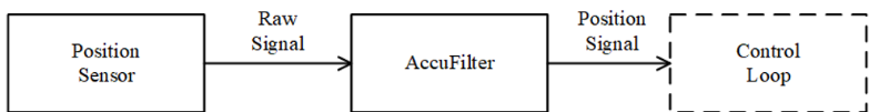
AccuFilter: The AccuFilter works to filter out the noise introduced by the position sensor. The raw signal produced by the position sensor is delivered to the AccuFilter. The AccuFilter filters out the noise and output the position information, as a feedback signal, to the control loop.
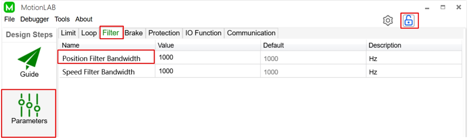
You can set the bandwidth of the AccuFilter on the "Parameters" page of the MotionLAB. Click here to learn more about How to setup the MotionLAB. Click the "Lock/Unlock Parameters" button to unlock the settings. Then you can configure the value of "Position Filter Bandwidth". Normally, set the position filter bandwidth to 10x larger than the position loop bandwidth to minimize the filter phase delay.
Notch Filter: The notch Filter works to filter out the resonant frequency of the system. The notch filter is a band-stop filter with a very narrow stop band and a very deep filter depth, of which the resonant center frequency (in Hz), the stop bandwidth (in Hz) and the filter depth (in dB) should be selected.
The resonant center frequency is the center frequency of the band that you want to filter out, which is usually set equal to the resonance frequency of the system.
The stop bandwidth is the width of the band that you want to filter out.
The filter depth is the attenuation multiple of the resonant center frequency. After the raw signal passes through the notch filter, the component of resonant center frequency will decay by a factor of the filter depth.
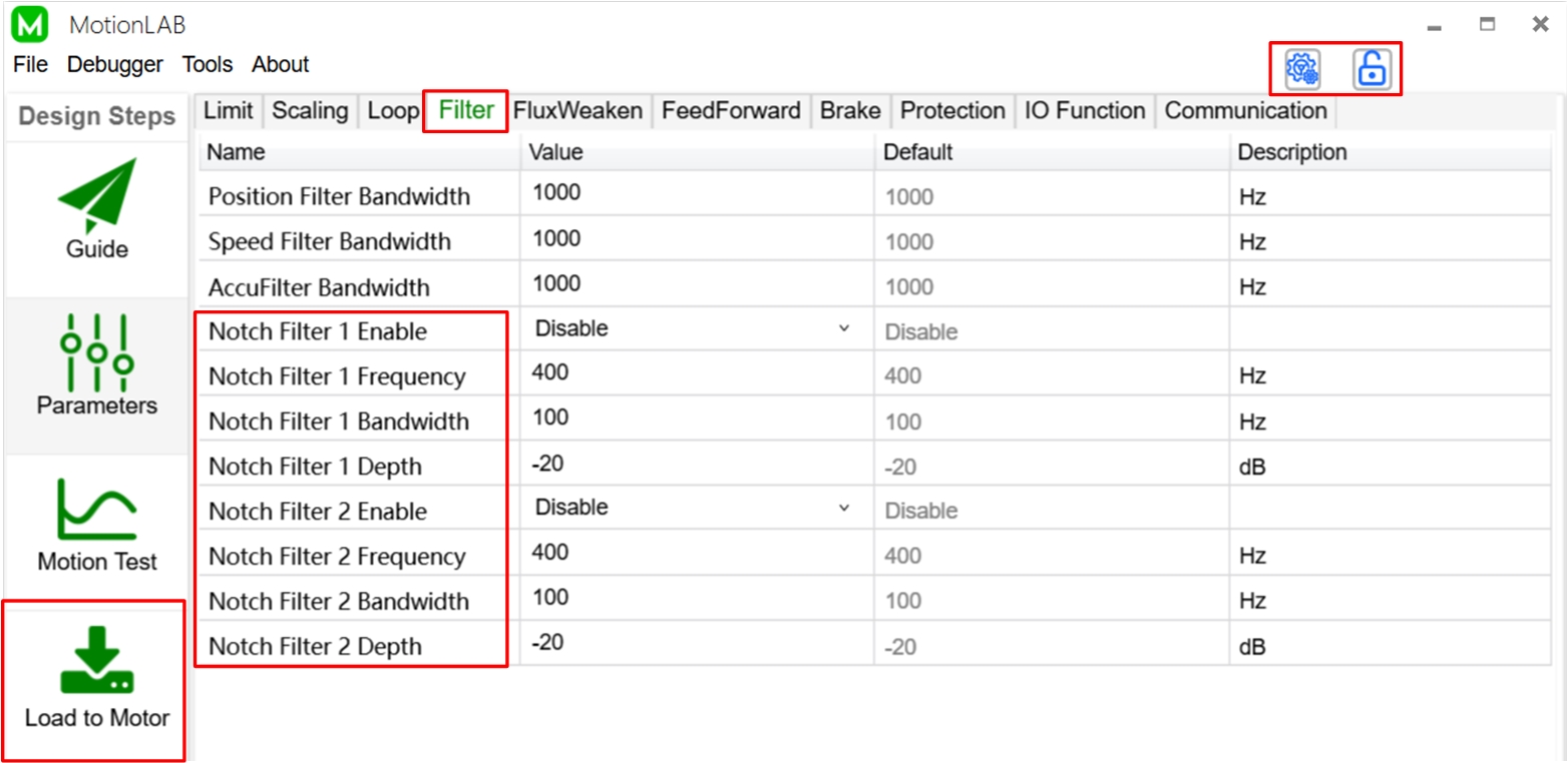
The MotionLAB integrates two notch filters connect in series. You can enable them and set the resonant center frequency (in Hz), the stop bandwidth (in Hz) and the filter depth (in dB) on the "Parameters" page of the MotionLAB. Click here to learn more about How to setup the MotionLAB. Click the "Basic/Advanced Settings" button to show the advanced parameters. Click the "Lock/Unlock Parameters" button to unlock the settings. Then you are able to enable and configure the notch filters.
After finishing the configuration, you can evaluate the system performance on the "Motor Test" page and save your settings to a file or download it to the motor on the "Load to Motor" page.
The theta bias is the sensor angle when the rotor is alignment with stator phase A. There are two ways to find the theta bias. One is to use "Auto Tuning". The measurement for theta bias will be included in the process of auto tuning. Click here to learn more about how to use the auto-tuning method.
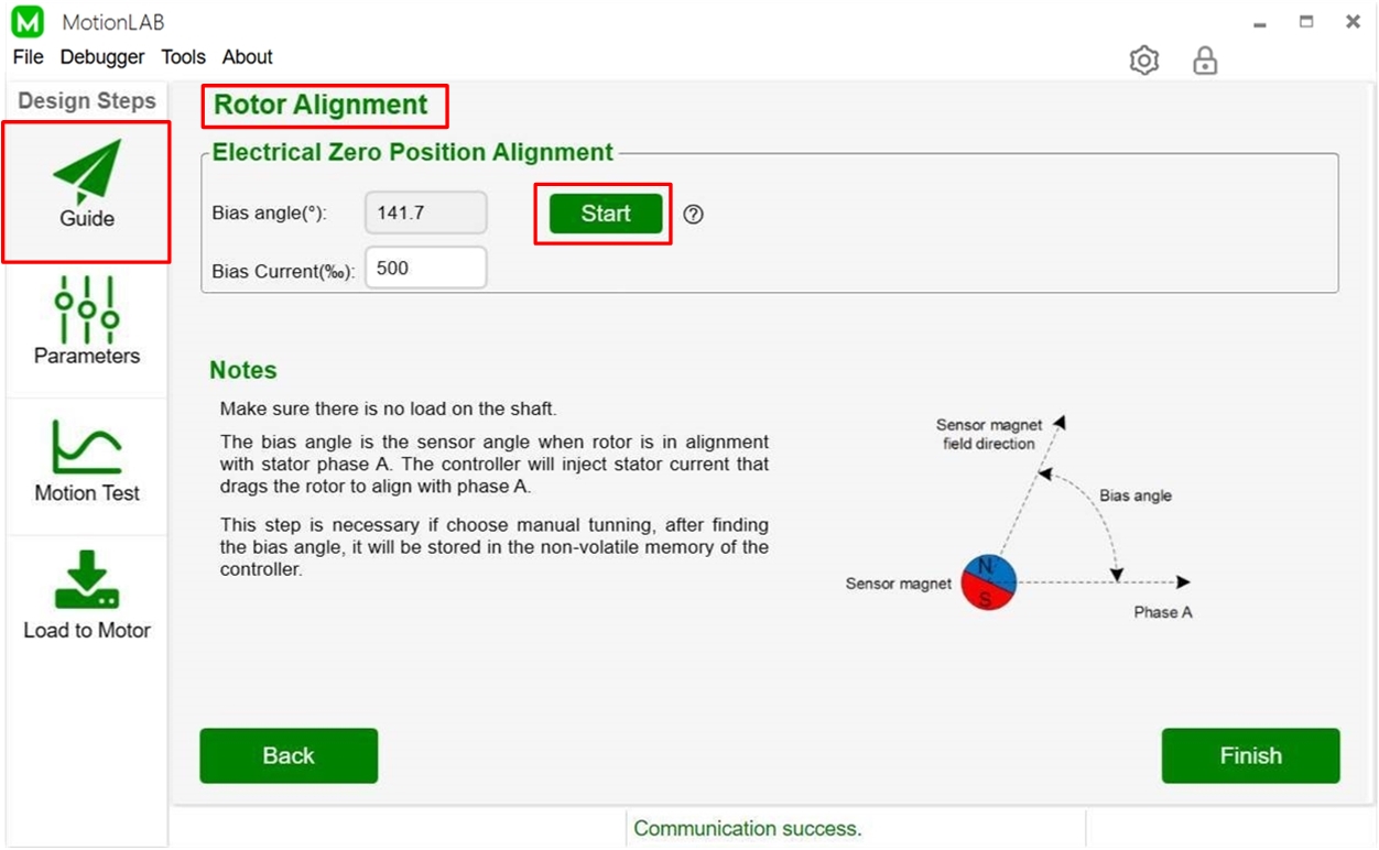
If you choose "Manual Tuning", you should do the rotor alignment step to measure the bias angle. You can turn to the "Rotor Alignment" part after clicking the "Manual Tuning" button on the "Guide" page. After clicking the "Start" button, the EZmotion module implements the following steps to find the theta bias
1. Apply current to motor windings to generate torque and drag the rotor to 300 degree electrical angle, then read the sensor data 1.
2. Apply current to motor windings to generate torque and drag the rotor to 60 degree electrical angle, then read the sensor data 2.
3. Calculate THETA_BIAS and THETA_DIR from sensor data 1 and sensor data 2.
4. Store THETA_BIAS and THETA_DIR to the module register.
The theta bias will be stored in the NVM (None Volatile Memory). Only need to do it once when the servo system is firstly setup. You can read it via "Register Access Tool". Please find it in the tool bar: Tools -> Register Access Tool. Type the register address of theta bias and click "Read button", then the "Data" will illustrate the value. The register information is listed below for your reference.

Validate your login
Log in to your account
Create New Account